AI Photogrammetry
Overview
Starting from Artec Studio 19, two new algorithms have been added to allow users to reconstruct 3D models from sets of photos and videos without a 3D scanner and a photogrammetry kit. Please be aware that projects created by this version might not be compatible with older versions of Artec Studio.
See also
For a quick start, please refer to the appropriate guide for your Artec Studio version.
If you are using Artec Studio 19, see:
If you are using Artec Studio 20 or Artec Studio Lite, see:
AI Photogrammetry leverages advanced algorithms to convert captured photos into detailed, feature-rich 3D models. On the way to a perfect 3D model, you can select the optimal processing mode (algorithm) based on the object type, its background and capture method.
AI algorithm without masks
For static small- to medium-sized objects standing on a stable background that does not change during capture, and that you photographed/recorded by walking around them (including close-ups), the AI algorithm without masks will deliver the best results.
This mode (where the Extract object from background option in Advanced settings is disabled) also performs best for objects with poor monotonous textures in static environments.
AI algorithm with masks
If the object was rotated (e.g., on a turntable), flipped, or moved to different positions during capture, or if the background was inconsistent or moving; and you did not take close-ups (i.e., maintained roughly the same distance from the object), we recommend using the AI algorithm with masks. You can use it by enabling the Extract object from background checkbox in Advanced settings. This mode will automatically separate the object from the background and produces a clean model. For best results, keep the full object within the camera’s field of view.
Note
This mode is most suitable for small to medium-sized objects.
Classic (non-AI) algorithm
For large objects or highly detailed scenes such as landscapes, use the Classic algorithm.
Note
We recommend using this algorithm for drone data sets.
Data Preparation
Using Scale References
Scale references are used to ensure that the 3D model is created with accurate real-world dimensions. Without them, the scale of the model will be arbitrary. By using scale references, such as scale bars or scale crosses, you can define the correct scale for your model.
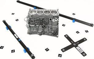
Figure 101 Scale references
Scale References Types
Scale references come in two types: Scale bars and Scale crosses.
A Scale bar allows you to obtain the correct scale for your model by using the distance between two targets. It defines the scale of an object but only along a single axis, making it useful for determining size but providing no information about orientation in 3D space.
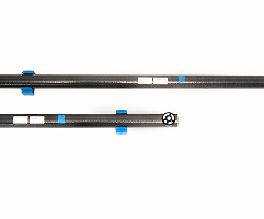
Figure 102 Scale bar
In contrast, a Scale cross provides a reference not only for the scale of an object but also for its position and orientation in 3D space. It consists of two intersecting scale bars. This comprehensive reference is particularly valuable when you need to determine both the size and alignment of an object relative to the scene.
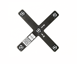
Figure 103 Scale cross
If you do not have a physical scale cross-reference, you can use a printed version, available as a PDF document at C:\Program Files\Artec\Artec Studio [version].
The file names are ASC A4.pdf for Europe and ASC US Letter.pdf for the USA.
Creating Scale References in Artec Studio
In order to detect the real object’s dimensions, you need to add scale references in Artec Studio before running the Create Preview algorithm.
First, open the scale reference creation dialog in Artec Studio. You can do it either by:
Going to File → Coded targets and scalebars, or
Going to Tools → AI Photogrammetry → Create Preview → Add in the Scale reference section. Once at least one scale reference is created, the Add button is renamed to Edit.
To add a Scale bar:
Define the IDs of the two targets, the distance between them (in millimeters), and the name of the scale bar. Note that the IDs must be unique and fall within the range of 1 to 516.
Click the Create reference button.
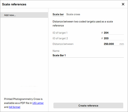
Figure 104 Creating Scale bar
To add a Scale cross:
Define the IDs of the two pairs of targets, the distance between them (in millimeters) in each pair, and the name of the scale bar. Note that the IDs must be unique and fall within the range of 1 to 516.
Finally, click the Create reference button.
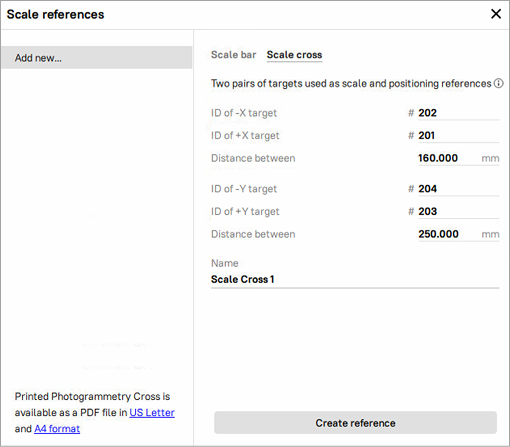
Figure 105 Creating Scale cross
The newly created scale references will appear in the list of all references on the left.
Capturing Data
General Recommendations
Here are some general recommendations on the capturing procedure, including lighting, capture methods, camera selection, and more:
Capture the object in a well-lit environment. Aim for a strong ambient light. The best light conditions are typically achieved by capturing outside on a cloudy day.
Make sure the entire object is in focus, with no areas blurred. If you find any blur, add more light to the scene, slightly close the lens aperture or do both.
Ensure the entire object fits within the camera frame and is separated from the background. Refrain from the scenarios where the majority of the frame is covered by the object with some parts of the background still visible, as this may confuse the object detector.
For the AI non-mask algorithm, closeups are allowed if they help capture fine details of the object’s geometry.
Capture the object from all the directions so that the algorithm receives a big variety of views. A good practice here is to imagine a virtual sphere around the object and try to capture images from different angles.
You can also turn the object to another side and repeat the capture to get full 3D reconstruction. In that case make sure that images from each object orientation are imported into Artec Studio as a separate photoset.
If your object lacks texture, ensure that the background contains many features.
Normally, 50-150 photos is typically enough to achieve good quality.
Note
Instead of photos, you can record a video of your object, considering the points mentioned above. Videos are treated as a set of frames and can be imported into Artec Studio in the same way as photos.
Good examples for objects:
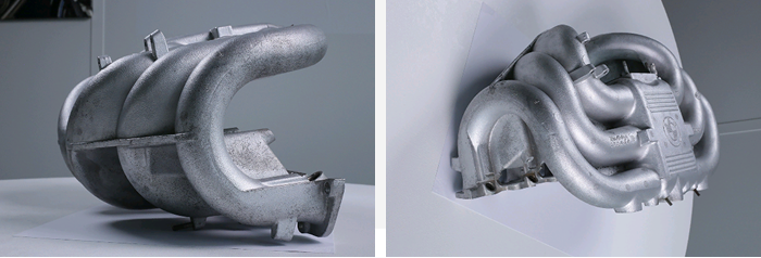
Figure 106 Good photos for the algorithm
Bad examples for objects:
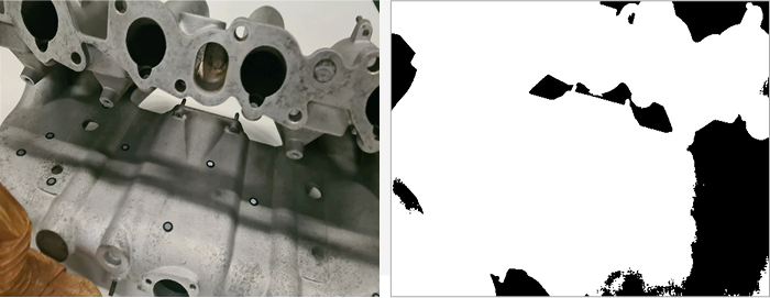
Figure 107 Closeups, when part of the object could be considered a background (allowed for the AI algorithm without masks)
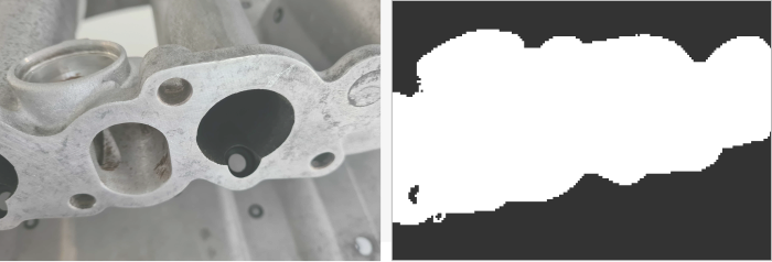
Figure 108 Overloaded background, when part of the background could be considered an object (allowed for the AI algorithm without masks)
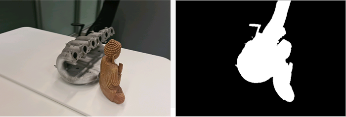
Figure 109 Good photos for the algorithm
Camera Selection
You can use multiple cameras to capture the same object. When importing the photos, Artec Studio will create a single Photos object for all images, regardless of which camera captured them.
There are no strict restrictions on using different cameras, but we recommend avoiding significant differences in the field of view (FOV). Ideally, the FOV difference should not exceed a factor of 7 to ensure consistent results. In some scenarios, using different types of cameras can be beneficial:
Drone and ground photography: Capturing aerial views with a drone and detailed ground shots with a regular camera provides comprehensive coverage of the object.
Wide-angle and standard Lenses: A wide-angle lens can efficiently capture a general scene, such as an entire room, while a standard lens can be used to capture detailed shots of specific elements, like a statue in the center of the room.
Importing Data into Artec Studio
To import photos/videos into Artec Studio, you need to go to File → Import → Photos and videos.
If a video file is imported, Artec Studio will create a photo set in the Workspace out of it. You need to specify frame rate at which photos will be imported from the video file by entering the desired value in the Frames extracted per second option of the Import video dialog.
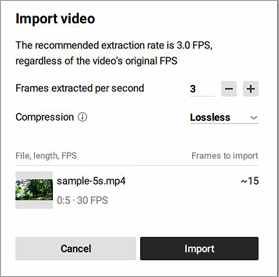
Figure 110 Import video dialog
Note
This value is not an original FPS value; it represents the extraction rate. The default value is 3, but you can adjust it. Keep in mind that increasing the value may reduce performance.
Also, you can select the desired Compression type: Lossless or Lossy. With Lossless Compression, the project size will be larger but the quality is fully preserved. In contrast, Lossy Compression reduces the project size by 20-50%.
Once you are ready, click the Import button. Selected files will be added to the Workspace as a new object of the Photos type. Video files will also be added as separate objects of the Photos type.
Viewing Photos/Videos
In Artec Studio, it is possible to assess each captured photo for adequacy of texture capturing or misalignments before reconstructing a 3D model. To inspect the quality of the imported photos, follow these steps:
In the Workspace panel, double-click a set of photos or right-click a set of photos and select the Show photos. The entire list of photos it contains will appear.
For each photo, its name, focal length, and camera data will be provided.
Note
By default, all objects in the 3D View window except the pictures of the selected set will be hidden. To see other objects, select the Show other selected objects option.
Double-click an individual picture to inspect it closer. It will be opened in a viewing pop-up
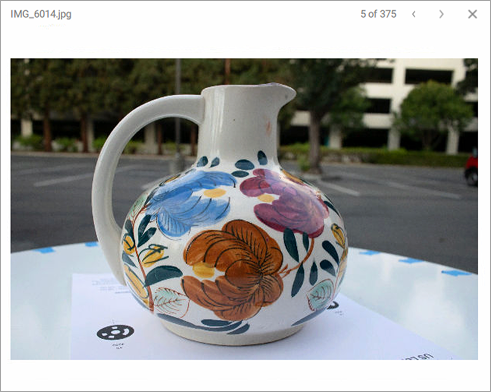
Figure 111 Viewing captured photos
Navigate between photos by clicking the right and left arrows in the top-right corner of the pop-up or by pressing the up and down arrow keys on the keyboard.
To exit the viewing mode, press either LMB or RMB and drag in any direction.
To delete a picture from the set of photos, click it in the Workspace panel by RMB and select Delete from the context menu. You can also press Delete on the keyboard.
Building Your First 3D Model
Once the data is prepared, you can start creating your first 3D model. Thanks to our algorithms, the process is very simple and divided into two consecutive steps: Creating Preview and Creating Model. The Create Preview algorithm registers photos by determining their position in space, resulting in a Photo Scan with aligned photos. The Create Model algorithm generates the final 3D model, which can then be post-processed and exported or imported.
Creating Preview
To create preview:
Select the imported photos in the Workspace panel
Open Tools → AI Photogrammetry
Click the gear icon of the Create Preview algorithm to open its settings window.
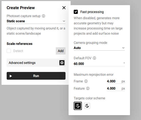
Figure 112 Create Preview settings
Before creating a preview of your future model, you can adjust the following settings:
Photoset capture setup defines how the object or scene appears across the dataset. To ensure correct photo alignment and reconstruction, select Rotated/Moved in each photo if the object was rotated (e.g., on a turntable), flipped, or moved to different positions during capture, and you are uploading all photos in a single photoset. Otherwise, select Unique for each photoset if you are uploading such data in multiple photosets.
If you select the Rotated/Moved in each photo or Unique for each photoset option, Artec Studio will prompt you to set up masks.
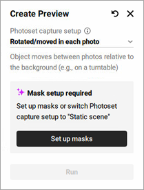
Figure 113 Setup masks required
Detect for the Scale references section determines whether scale references will be analyzed or not. Refer to Using Scale References on how to create and use scale references.
Fast processing speeds up processing but may reduce geometric accuracy
Camera grouping mode defines how the software interprets which photos were taken by the same camera. This helps the algorithm handle variations in camera parameters, especially when metadata is missing or unreliable.
Auto assumes that all photos were taken with the same camera. Suitable when there is no metadata and the images are likely from a single device without focal length changes.
Shared per photoset treats each photoset as taken with a different camera or with significantly different camera settings. Recommended when switching phones, lenses, or focal lengths between photosets.
Individual considers every photo as taken with a different camera. Best used when camera parameters, such as focal length, may vary between individual photos.
Default FOV specifies the camera’s field of view, used when this information is missing or unreadable from photo metadata. The default value is 60°.
Frame specifies the maximum allowable deviation for matching points between individual frames or photos. It limits how much point positions can vary within a photoset; if the reprojection error exceeds this value, the program may mark such frames as mismatches. The default value is 4.000 px.
Feature sets the maximum error for matching object features, such as contours or textures; lower values lead to more precise reconstruction of object details. The default value is 4.000 px.
Target color scheme defines the color scheme of the targets for detection, with options for white on black or black on white.
Click Run to launch the algorithm
Once calculation is finished, a Photo Scan object appears in the Workspace panel. This photo scan is colored so you can see the general shape of your object.
Double-click on the newly created Photo Scan object in the Workspace panel and modify the cropping box around the object to adjust the region of reconstruction.
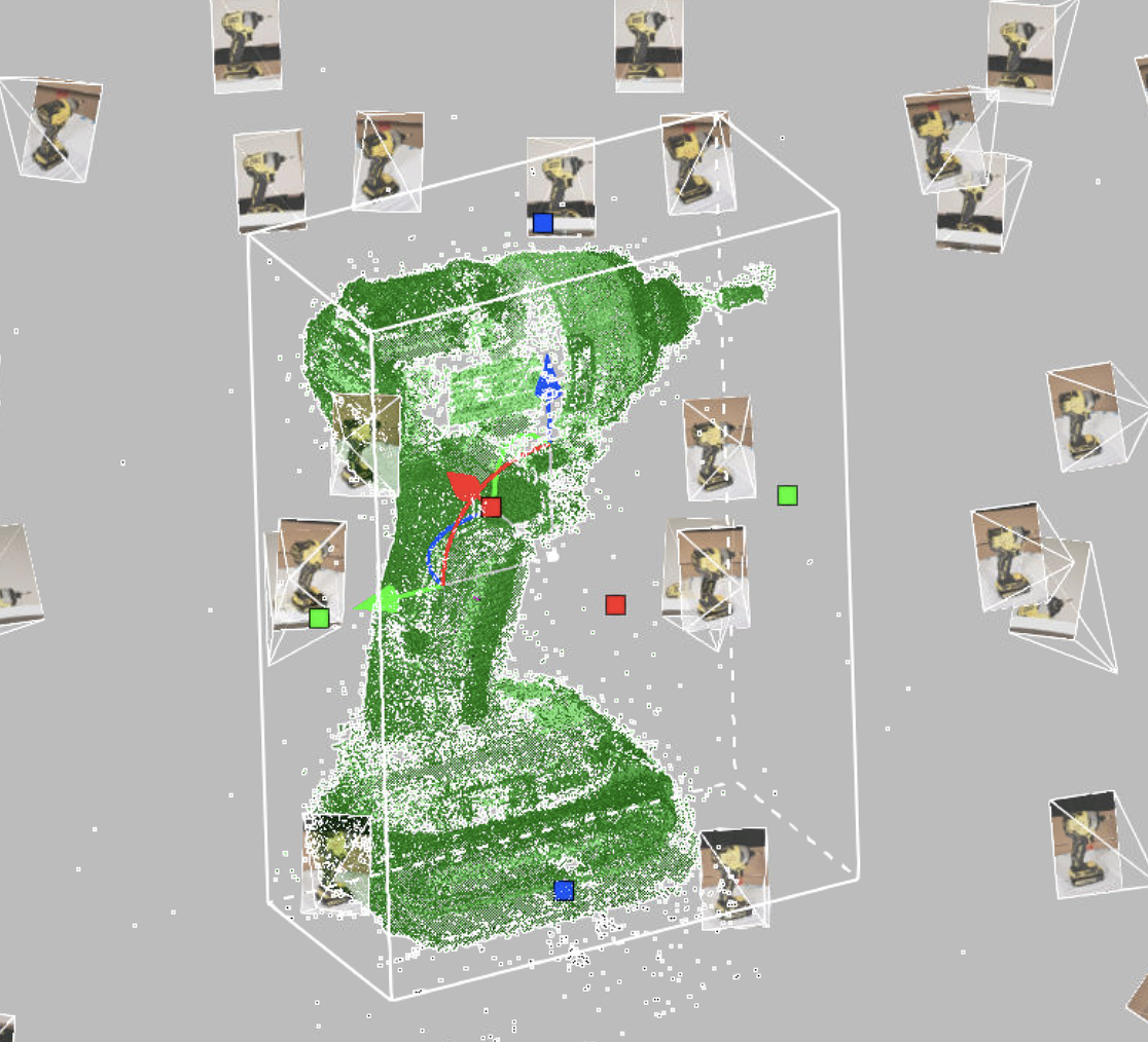
Figure 114 Created Photo Scan in the cropping box
Double-click an individual picture to inspect it closer. It will be opened in the viewing mode:
To compare the Photo Scan object’s texture with a reference photo or check for misalignments, use the Show photo toggle or press Ctrl+Q. The reference photo will be hidden.
To zoom in and out, use Scroll wheel.
To move the picture, hover over it and drag it holding down Scroll wheel.
To exit the viewing mode, press either LMB or RMB and drag in any direction.
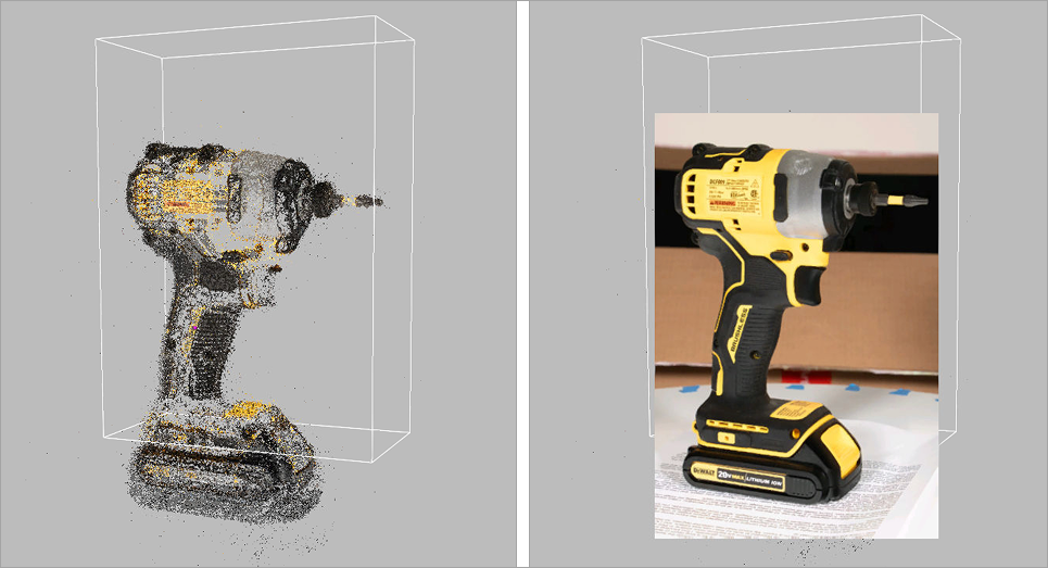
Figure 115 Photo Scan: viewing mode
Creating Model
To create model:
Select the previously created Photo Scan in the Workspace panel
If the panel is closed, open Tools → AI Photogrammetry
Click the gear icon of the Create Model algorithm to open its settings window.
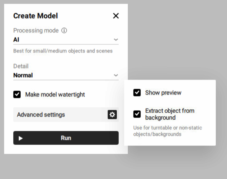
Figure 116 Create Model settings
Before creating your future model, you can adjust the following settings:
Processing mode defines which algorithm (AI or Classic) will be used to create a 3D model from photos, depending on the type of object and capture method.
AI: best for small to medium-sized objects and static scenes. Suitable for both “with masks” and “without masks” modes depending on background consistency.
Classic: best for large objects and highly detailed scenes such as landscapes or drone data sets.
Refer to Overview for more information on photogrammetry and algorithm types that Artec Studio suggests.
Detail: defines the level of details in the reconstructed model. In most cases, the Normal option would be enough. Use the High option if you need extra level of details or better reconstruction of thin structures of the object. The High option might result in more detailed but noisier reconstruction compared to the Normal option. It also takes longer to calculate.
Show preview enables a real-time preview
Extract object from background defines whether the object will be automatically separated from the background, resulting in a clean model. Recommended for turntable or non-static objects/backgrounds.
Click Run to launch the algorithm
The next step is to texture the model the same way as other models in Artec Studio. To texture the model, refer to the Texturing section.
Once calculation is finished, a 3D model appears in the Workspace panel and in the 3D view window.
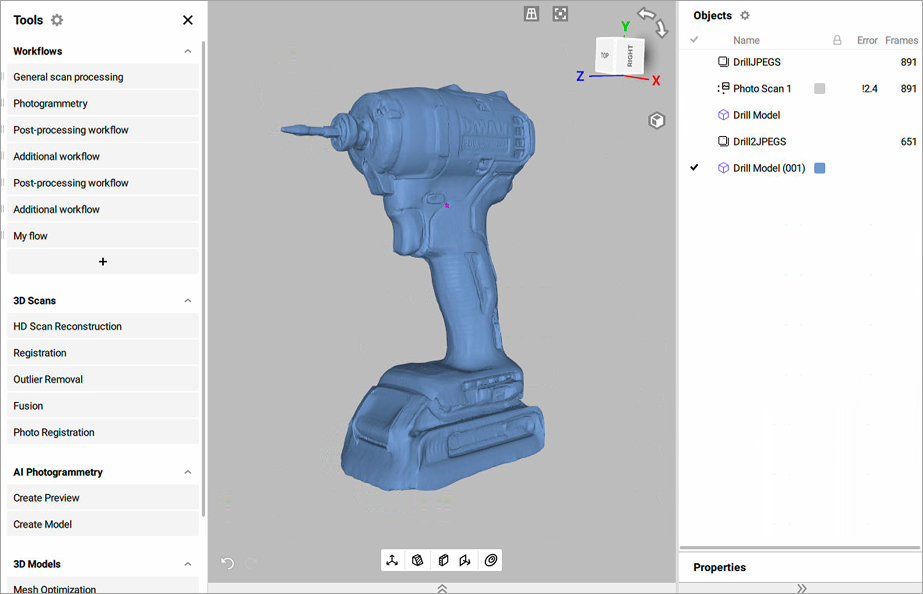
Figure 117 Created model in Artec Studio
Project Masks
Artec Studio allows to project object on masks. A mask defines which part of the photo belongs to the object you want to turn into a 3D model. It separates the object from the background. In AI Photogrammetry, masks help the algorithm focus only on the object, providing the high quality of the 3D model. The masks projection feature enhances the accuracy of 3D mesh reconstruction by leveraging masks created from the registered preview (Photo scan). This tool is particularly useful when the initial mask detection during the Create Preview algorithm fails or produces inaccurate results. By projecting new masks onto the created 3D model, users can exclude unwanted details, such as background elements, and regenerate a cleaner, more precise 3D model.
The typical workflow would be:
Run the Create Preview algorithm to generate a Photo scan. For preview settings, refer to Creating Preview.
Identify inaccurate or faulty masks detected on certain images and exclude these images from the creating model process
To disable these masks:
Double-click the created Photo scan in the Workspace panel
Click a mask that you need to disable or Shift-click to select multiple masks
Right-click on the selected masks
Select the Disable mask option
Run the Create Model algorithm to generate a 3D model. For model settings, refer to Creating Model.
Project masks onto the excluded images based on the 3D model
To project masks:
Ensure that the created 3D model and the Photo scan are selected in the Workspace panel
Double-click the Photo scan in the Workspace panel
Enable the previously disabled masks by selecting them and choosing the Enable mask option from the right-click context menu. For a single mask, click the crossed rectangle icon in the upper-right corner of its preview.
Analyze the other masks and select the Project masks option from the right-click context menu
Recreate the 3D model with improved quality and accuracy by running the Create Model algorithm
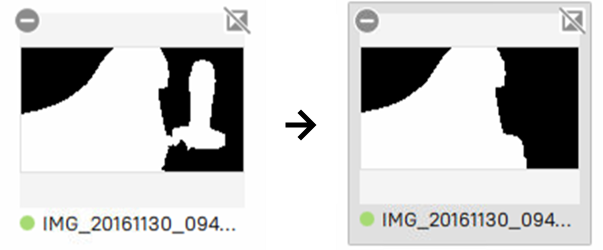
Figure 118 Example of projection masks before and after