Data Processing
The resulting model may contain surface defects. Artec Studio Lite provides a number of tools to correct such errors:
Smoothing brush enables manual smoothing of the surface areas with the most noise. For more information, refer to this section of the Artec Studio User Manual.
Eraser removes unnecessary parts of the model. For more information, refer to this section of the Artec Studio User Manual.
Precise positioning positions the model in the global coordinate system. For more information, refer to this section of the Artec Studio User Manual.
Mesh optimization improves the quality and performance of your 3D model by combining several tools - Small-object filter, Hole filling, and Mesh simplification. It removes small artifacts, fills holes, and reduces polygon count while preserving accuracy and texture. For more information, refer to this section of the Artec Studio User Manual.
Fix holes generates new geometry to close gaps in the model surface. For more information, refer to this section of the Artec Studio User Manual.
Mesh smoothing filters low-amplitude noise over the whole model. For more information, refer to this section of the Artec Studio User Manual.
In this section, we will focus on the most essential algorithms for common workflow. For detailed information about all available algorithms and their advanced parameters, please refer to the Artec Studio User Manual.
Editing
To remove unnecessary parts of the model:
Open the Editor panel using the side toolbar.
Open the Eraser tool by clicking
 or by hitting E.
Select the model in the Workspace panel.
In the Editor panel, choose the required selection type (e.g., 3D)
Hold down Ctrl and use Scroll wheel to adjust the tool size. Paint with Ctrl+LMB to create a selection.
To clear all selections, click Deselect.
Figure 22 Selected area to be erased
Click Erase to eliminate the area highlighted in red
To undo changes, click  in the 3D window or hit Ctrl+Z.
Each click of the Erase button generates a command history entry.
To undo several operations, use the dropdown menu of button and select the lowest entry.
in the 3D window or hit Ctrl+Z.
Each click of the Erase button generates a command history entry.
To undo several operations, use the dropdown menu of button and select the lowest entry.
Note
You can also set an Eraser lock to one or more objects in the Workspace panel. The Eraser tool will not affect any object in the Locked object  status.
Positioning
Automatic Positioning
Before exporting the model, it is important to position it correctly in the global coordinate system. This ensures that the object is displayed accurately in external software that relies on global coordinates.
Before using the Precise Positioning tool, you must first create a suitable primitive. To do this, go to Construct → Create and select or create the primitive that best fits your alignment needs. For example, you can create a plane (e.g., XY plane), to which the model can then be snapped or aligned.
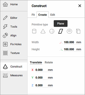
Figure 23 Create plane
The Precise Positioning tool allows you to align the model relative to these primitives, ensuring precise placement. This is particularly useful when you want to:
Export the model to CAD software (for example, after using the Auto Surface function to convert a mesh to a CAD-compatible format).
Perform accurate measurements in external software.
Ensure the correct orientation of the model for visualization or collaborative workflows.
If desired, you can skip using primitives and manually set the model’s position with the Transformation Tool (See Manual Positioning), specifying its coordinates and rotation relative to the global coordinate system.
To position a model based on the created primitive (plane):
In the Workspace panel, select the model and the primitive you want to align.
Open Editor → Precise positioning.
In the Primitives box, select the CAD primitive you intend to position. Below the Primitives box you will see the available positioning options (see Table 1 for details), which appear as buttons and vary with the type of the selected primitive.
Click either of the self-explanatory positioning buttons. Artec Studio Lite will position the primitive in accordance with the selected option and disable this button. You will see the alignment information in the Primitives box next to the name of the selected primitive.
Every positioning action is recorded in the local history, so you can undo or redo it:
To undo an action, use Edit → Undo, click
in the 3D window, or Ctrl+Z.To redo an action, use Edit → Redo, click
 in the 3D window, or Ctrl+Y.
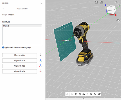
Figure 24 Editor → Precise positioning: the model and the primitive.
Button |
Purpose |
Hot Key |
|---|---|---|
Move to origin |
Place the selected primitive’s point to the coordinate origin. |
|
Align with X/Y/Z |
Align the primitive with the respective axis. |
X, Y or Z |
Align with YOZ/XOZ/XOY |
Align the plane primitive with the respective coordinate plane. |
YOZ, XOZ or XOY |
Any |
CAD primitive that you first align with any coordinate axis or plane is considered primary. A primary object will be given a priority when conflicting alignments occur. |
P |
Make primary |
Make another object primary and remove this status from the current primary one |
|
Reset origin |
Undo the Move to origin action. |
|
Invert direction |
Invert direction of the axis or plane in the applied alignment |
I |
Reset alignment |
Reset all the positioning actions applied to the primitive |
Manual Positioning
The Transformation tool allows you to move, rotate, scale and mirror objects relative to the global coordinate-system axes.
To access this tool, open the Editor panel and select Transformation tool or hit T. The panel will open, displaying four tabs that correspond to different modes for altering the object position in the global coordinate system. The name of the active mode appears at the bottom of the 3D View window.
To revert your changes inside the tool, use the Reset button.
Artec Studio Lite applies changes when you leave the tool.
Use the (Undo) button in the 3D window or hit Ctrl+Z.
Hint
To quickly move objects to the origin and align them with the camera viewport, use the Auto-position button.
Translate
To enter the Translate mode, click the Translate tab or hit T. Three input fields will appear in the Editor panel showing the current origin coordinates (in millimeters) of the local coordinate system. The initial position of the local coordinate system will be in the center of the global one. To translate an object, do either of the following:
Enter the new coordinate values for the local system using the input fields in the Editor panel. To adjust the position only along a specific axis, first hit the corresponding X, Y or Z key.
Translate the object in the 3D View window by dragging the corresponding gizmo control
Square in the center to move it freely
Arrow to move it along a specific axis
Lines between arrows to move it along the two axes simultaneously
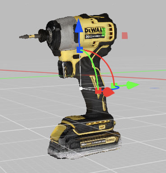
Figure 25 Transformation gizmo
Note
Orienting the object may be easier if you first specify a new position for the origin of the local coordinate system: double-click on the desired surface point in the 3D View window.
Rotate
To enter the Rotate mode, click the Rotate tab or hit R. Three input fields containing the Euler-angle values will appear in the Editor panel. Initially, all values are set to zero. To rotate the object, do either of the following:
Enter the new angle values (in degrees) using the input fields in the Editor panel.
Drag one of the three gizmo circles to rotate the object. Hitting the key that corresponds the required axis (X, Y or Z) will hide the controls for the other axes.
Note
Orienting the object may be easier if you first specify a new position for the center of the local coordinate system: double-click on the desired surface point in the 3D View window.
Scale
To enter the Scale mode, click the Scale tab or hit S. A single input field with the current scale value (1.000) will appear in the Editor panel. You have two options for scaling the object:
Enter the new scale value in the field.
Drag the origin of the gizmo control or either of its round ends in the 3D View window.
Aligning
The Align Tool allows you to align any imported model with the photogrammetry result, or alternatively, align two photogrammetry models. This is useful when you want to combine data from different sources — for example, merging a photogrammetry model with a 3D scan.
A typical use case is combining a large photogrammetry model captured by drone with a detailed scan taken by a terrestrial 3D scanner. For instance, you can create a 3D model of a castle and its surrounding landscape using photos from a drone, then scan the lower part of the castle with Artec Ray II. After aligning the two datasets with the Align tool, you can joing them together again using Tools → Fusion to obtain a complete model.
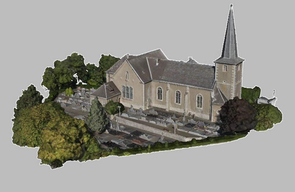
Figure 26 The landscape model with combined data (drone footage and 3D scanning)
For more information on using the Align tool, please refer to the Alignment section of the Artec Studio User Manual.
Optimizing
In Artec Studio Lite, several tools, including the Small-object filter, Hole filling, and Mesh simplification, have been combined into a single tool called Mesh optimization. Using all of them at the same time is optional, but it can proide you with better output when running the algorithm.
To start working with Mesh Optimization tool, select only the model you are currently editing in the Workspace panel, open Tools → Mesh Optimization. Once you set up all parameters that you need, click the Run button either on the pop-up of the Mesh Optimization tool or next to its name on the Tools panel to run Mesh Optimization algorithm.
Adjust the number of triangles in the resulting model, displayed in the Target quantity of triangles field, by dragging the Triangle quantity ratio slider.
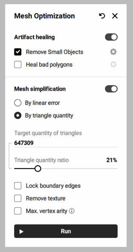
Figure 27 The Mesh Optimization window
Texturing
One of the must-have steps in creating your first 3D model is texturing it. To apply a texture to a model:
Open the Tools → Texture panel.
Select a model from the Model to texture list. Artec Studio Lite will apply the textures to this model. The model selected in the Workspace panel will automatically be active in this list.
In the Texture source section, the photo scans from which you created the model will be selected. Otherwise, select the necessary source data manually.
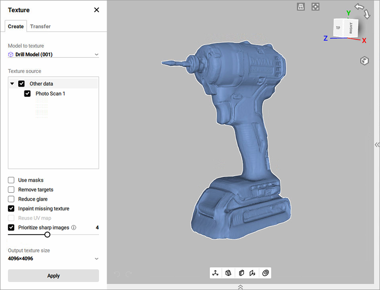
Figure 28 Texture panel. Texture source section
Select the required Output texture size and other options as necessary.
Click Apply to start the texturing process.
After the texturing is complete, you can adjust the texture on the model (see Figure 29).
You can adjust the following texture parameters by changing the value of the followinig sliders:
Brightness
Saturation
Hue
Contrast
Gamma correction
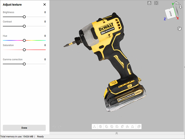
Figure 29 Texture adjustments.
The initial position of the Hue slider corresponds to the current texture color. Dragging it left or right corresponds to rotation counterclockwise or clockwise, respectively, on the color wheel.
After making the necessary changes, click Done to transfer the resulting textured model to the Workspace panel.
To reopen the texture-adjustment dialog, follow the steps:
Select a textured model in Workspace.
Use RMB to call the context menu.
Select the Adjust texture option from the list.
Measuring
To evaluate the reconstructed 3D model, it is possible to make measurements.
Artec Studio Lite offers a number of measurement tools, including
Distance
Linear distance
Thickness
Geodesic distance
Sections and Volume
Distance map
Section analysis
The corresponding buttons are located in the upper part of the Measures panel.
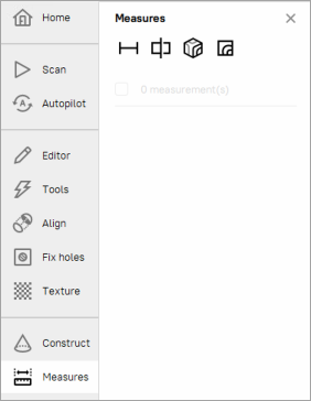
Figure 30 The Measures panel.
To work with these tools:
Mark the
 checkboxes of each desired scan or model to display them in the 3D View window.
Select the measurement tool you need and click on the object surfaces to create measurement lines, planes, etc.
Linear Distance
When you select Measures → Distance ( ), the linear measurement will be used by default. Don’t mark the Geodesic checkbox.
The linear-measurement tool allows you to measure:
the distances between selected points
the thickness of a model
the total length of a polyline determined by a sequence of points
You can enter a name for the new measurement by typing it in the Name and color field. Click on the color circle next to the field to choose a color of the measurement projection.
The application creates new measurements with default names Linear 1, Linear 2 and so on.
To measure distances between points,
Use LMB to sequentially set the points on the model in the 3D View window. The application will add these points to the current point list (in the Measures panel), which will also display linear dimensions and point coordinates.
When you roll the cursor over any one of these points in the 3D View window, the point will be highlighted; you can then drag it to another location using LMB. When you release the mouse button, the point will fix to its new location.
Note
You can’t set a point outside the object’s surface; in this situation, if you release the mouse button, the point will return to its original position.
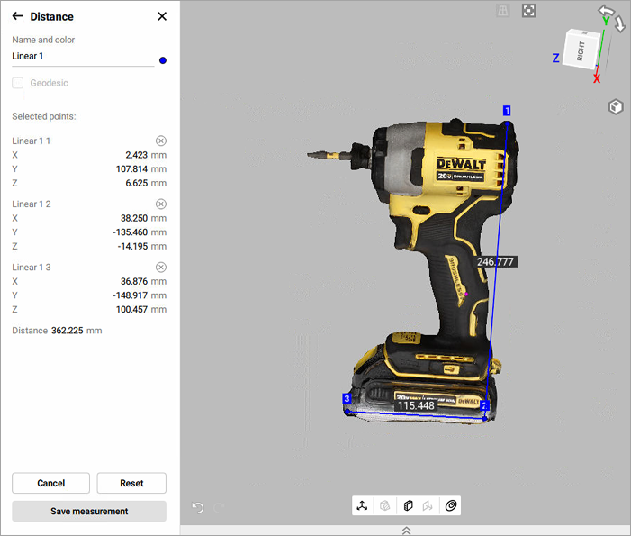
Figure 31 Linear measurement.
After you click Save measurement, the application will return to the original Measures panel and will display a list of all saved measurements along with editing and deletion options.
For other mesurement tools, please refer to the Artec Studio User Manual.